Database diagrams
Database diagrams graphically show the structure of the database and relations between database objects. You can generate a diagram for a data source, a schema, or a table. To create relations between database objects, consider using primary and foreign keys.
The following video gives a short overview of diagrams in DataGrip.
You can save the generated diagrams in two formats: UML and PNG. The UML format is an internal format developed specifically for DataGrip. It is not supported by other products. If you want to share the created diagram, consider using PNG.
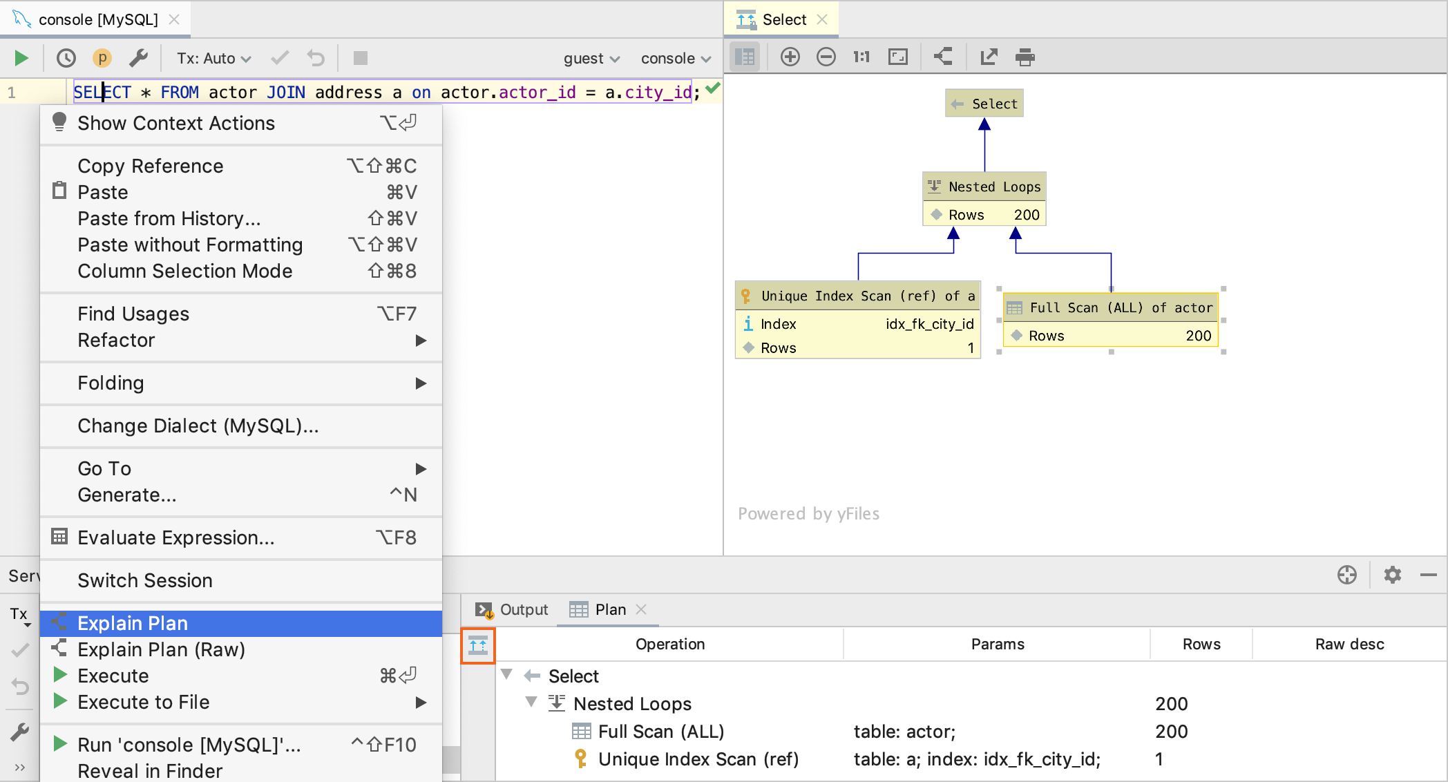
Also, you can build execution plans. Execution plan is a set of steps that were used to access data in a database. DataGrip supports two types of execution plans:
-
Explain Plan: the result is shown in a mixed tree and table format on a dedicated Plan tab. You can click the Show Visualization icon (
 ) to create a diagram that visualizes the query execution.
 -
Explain Plan (Raw): the result is shown in a table format.
Generate a diagram for a database object
-
In the Database Explorer (), right-click a database object and select .

Build a query plan
-
Right-click an SQL statement, and select Explain Plan.
-
In the Output pane, click Plan.
-
By default, you see the tree representation of the query. To see the query plan, click Show Visualization
, or press Ctrl+Alt+Shift+U.
Show execution plans
-
To create an execution plan, right-click a query in the editor and select Explain Plan. If you want to create a diagram for the query, click the Show Visualization icon (
).
Enable column comments
-
Generate a diagram. For more information about generating a diagram, see Generate a diagram for a database object.
-
Click the Comments button (
 ).
).
Apply colors to diagram objects
-
In the Database Explorer (), right-click an object and select Color Settings.
-
Select a color and click OK.

Save diagrams in the UML format
This UML format is an internal format supported only by DataGrip.
-
Right-click a diagram and select Save UML Diagram.
To open the saved diagram, drag the UML file to the editor.
Save diagrams in the PNG format
-
Right-click a diagram and select Export to Image File.
Diagram configuration settings
To configure the default visibility settings and layout for diagrams, open settings by pressing Ctrl+Alt+S and navigate to .

Change the color of a link
-
Open settings by pressing Ctrl+Alt+S and navigate to .
-
Click Edges//Generalization edge.
-
Click the color picker near the Foreground checkbox.

Content pane
Select the checkboxes next to the elements to be shown on diagrams.
| Item | Description |
|---|---|
| Show Difference | |
| Details | If this checkbox is selected, all the specified details of the elements will be shown in the UML class diagram for a revision. If this checkbox is not selected, only node elements will be included in the diagram. |
| Database Schema Diagram | |
| Key columns | For the primary key columns to be shown when a diagram opens, select this checkbox. When viewing a diagram in the editor, use |
| Columns | For the columns other than the primary key columns to be shown when a diagram opens, select this checkbox. When viewing a diagram in the editor, use |
| Graphical Explain Plan | |
| Attributes | Toggles the display of query attributes on a query map. These attributes can be a number of rows, index names, or any other additional information about the query.  |
Controls
| Item | Description |
|---|---|
| Default layout | Select the desired layout from the Default layout list. Node elements in newly created diagrams will be arranged according to the selected layout. |
| Default scope | Select scope from the Default scope list. Specifying a scope helps you avoid showing in diagram the unnecessary hierarchies. You can define scopes for your project in the Scopes page of the Settings Preferences dialog. |
| Fit content after layout | If this checkbox is selected, then after applying a layout selected on the diagram context menu, all diagram elements will be resized to fit into the current diagram area. In diagram, use the |
| Do relayout when new elements were added | If this checkbox is selected, diagram layout will be performed automatically after adding new elements. |
Last modified: 11 October 2021
Source: https://www.jetbrains.com/help/datagrip/creating-diagrams.html
Posted by: shadinguardsene0194265.blogspot.com
